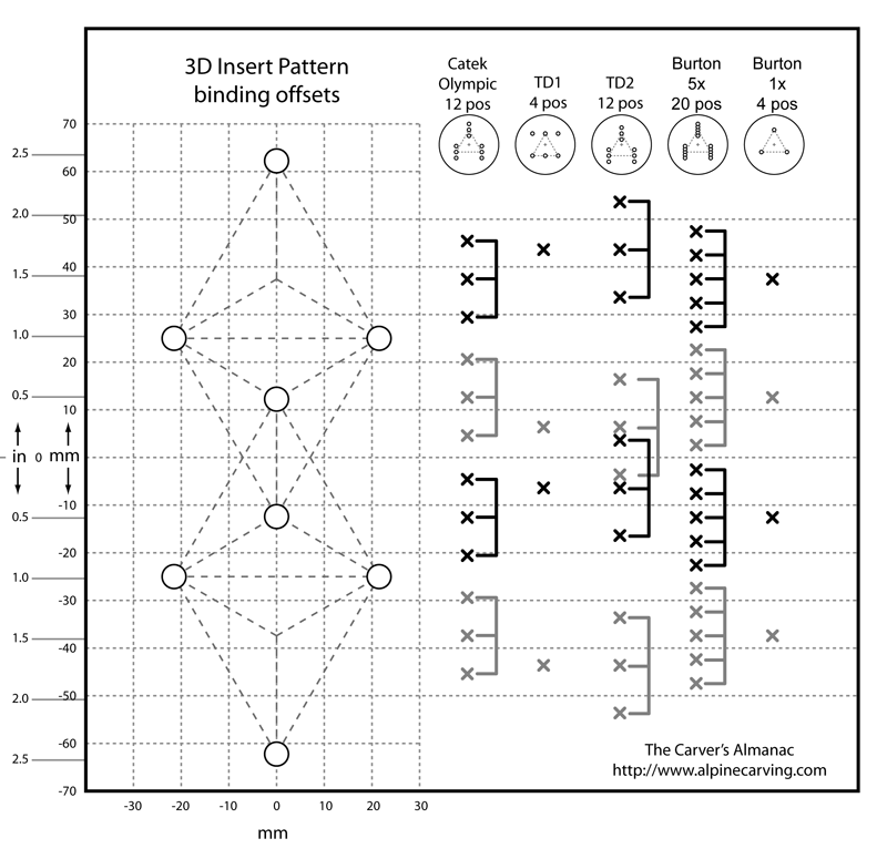
3D binding offset map
This chart shows possible fore/aft locations of various bindings
when used with the Burton 3D insert hole pattern. For each binding, a vertical
series of x's indicates locations where the center of the binding disk can be
positioned. The x's are grouped - each group uses the same 3 board inserts,
but different holes in the binding disk.

At first glance, this chart would appear to be a useless exercise in trivial minutia. But closer inspection reveals hidden subtleties:
- Burton binding disks with a single set of holes, and Bomber TD1s have
large spacing between some fore/aft locations, which means you might not be able to dial in
the ideal stance width and setback. It's another reason to upgrade from TD1s to TD2s.
- For TD1s, the possible locations for the binding disk center holes was highly constrained, which explains the nonuniform fore/aft positions. Because of the binding disk hole placement, you don't get additional positions by rotating the bindings disks 180º (which you could do for a 0º cant disk)
- For TD2s, more uniform spacing would result if the hole pattern on the disk were shifted a few mm toward the edge near the center holes, but doing so would also reduce the total possible range.
- For TD1 and TD2, you can theoretically rotate the binding disks 120º, which provides additional fore/aft positions, but those positions will also offset the binding on the board widthwise, and may cause weird stress patterns on the inserts.
- There is a 1:1 scale pdf file of the image. You can print it out on a transparency, then overlay the transparency on top of the board, aligned with the inserts. Why you would want to do this, I have no idea- it's just a random thought.
Back to The Carver's Almanac

